In TrEd, the way a tree is displayed is controlled by so called display stylesheets. Display stylesheets define what text is rendered as node and edge and how labels, the way tree edges are drawn (much more can be achieved than just straight lines connecting a node and its parent node), shape of the nodes, coloring, content of a tool-tip (hint) shown when mouse pointer lingers over a node, as well as the content of text window displayed above the tree. All these properties of the visual representation of the tree are specified using so called styling patterns.
TrEd maintains a list of stylesheets from which stylesheets can
selected and swithched between. The easiest way to select a
stylesheet is to click on the stylesheet menu-button shown on
the picture Figure 4, “Switching between stylesheets” below. This button
can be found on the right side of the toolbar next to the
 button.
Another way to select a stylesheet is using
->.
button.
Another way to select a stylesheet is using
->.
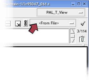
The stylesheet currently selected on the picture and named <From File> is always present. This is a rather virtual stylesheet whose content is always the styling patterns specified in the currently displayed file (some - but not all - file formats such as FS allow storing stylesheet information). These file-specific stylesheets are rather hard to maintain especially when one is working with hunderds of files. It is thus much more convenient to create a named stylesheet that can be used for any file at any time.
To create a new named stylesheet (based on the current pattern settings), select an item labeled <New From Current> from the stylesheet list and fill a name into the displayed dialog entry. The new stylesheet immediatelly appears as the selected item in the list.
While a file-specific stylesheet is stored directly in the FS
file, named stylesheets are all saved in a file called .tred-stylesheets in user's home
directory. This file is updated every time a named stylesheet
is added removed or edited. Currently selected named stylesheet
can be completely removed from the list by selecting <Delete Current> item from the
pattern-set list.
Selected stylesheet can be edited in a stylesheet editor which
appears when button is pressed or ->
menu command issued.
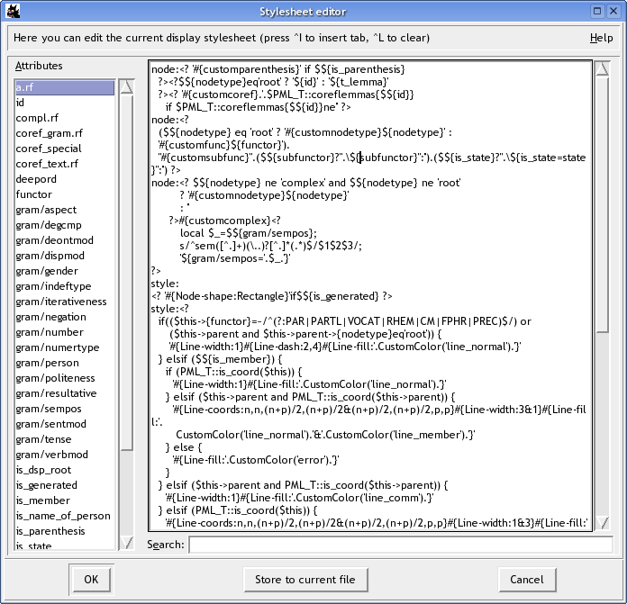
The dialog window contains two main elemens: a list of node attributes and an editor of stylesheet paterns. Double-clicking an attribute in the list inserts an attribute reference at the current cursor position in the pattern editor.
A stylesheet consists of one or more styling patterns. A styling pattern begins with a pattern prefix which must occur at the very beginning of a line (no whitespace allowed) and is followed by a comma. After the comma follows a body of the pattern.
TrEd recognizes the following pattern prefixes (described in
detail below): node,
edge, style, text and rootstyle.
If any other prefix is used, TrEd ignores the pattern.
node:defines a line of text to be displayed under each node of the tree. A stylesheet may contain one or more
node:patterns, in which case the lines are displayed in the tree one under another in the order as they appear in the stylesheet.edge:defines a line of text displayed across (or beside) the edge connecting each node with its parent. Of course, this label is not rendered for the root node. Likewise
node:patterns, severaledge:patterns may be specified. Note however thatedge:patterns make the tree look quite wide and it is usually better to avoid them.style:defines a pattern affecting the visual representation of various components of a tree.
style:patterns do not result in any text visible on the screen but may contain special tree styling instructions described below. These instructions may dynamically alter the appearance (such as coloring, line thickness, etc) of the nodes, edges and text labels.text:defines a portion of the text representing each node in the text window above the tree.
rootstyle:defines a pattern which behaves quite the same as a
style:pattern but is only interpolated once (for the root node), applies to every node of the tree, but the styling instructions defined in this pattern have lower precedence than those ofstyle:patterns.hint:defines the content of a tool-tip shown when mouse pointer lingers over a node. No styling instructions are allowed in the
hint:patterns.
Pattern body consists of a text which is interpreted as follows:
<?code?>Perl-code expansion. This sequence may encapsulate any Perl code. The code is interpreted in the time of evaluation of the pattern (i.e. just before the line is actually to be displayed) and the result returned by the code replaces the code sequence in the pattern.
Note that the returned value may contain other special sequences, but can't contain another
<?sequences....?>The
codeis subject to very similar rules as macros in TrEd (see Section 14, “User Macros”). One may refer to any attribute value of the node currently being styled as either$${orattr}$this->{. The current node object itself can be refered to asattr}$this(so e.g.$this->parentgives access to its parent). Regardless of what context is currently selected, the code occuring in the styling patterns is always evaluated within theTredMacronamespace. In order to call a user-defined macro from another namespace, it is therefore necessary to use a complete namespace (package name) prefix. So, a call to a macro namedbarfrom a package (context)Fooshould look likeFoo::bar(.arguments...)${attr}Attribute reference. Any occurence of this substring is replaced by current node's value of attribute named
attr. Using attribute references only makes sense in thenode:,edge:,text:andhint:patterns. In the labels rendered fromnode:,edge:patterns, this reference is actually linked with the corresponding node's attribute, so double-clicking on the displayed value in the tree shows a dialog where the attribute value can be edited.${attr=value}This is a special form of an attribute reference, which is only useful in
node:,edge:patterns. It always renders asvalue, but still retains the reference to the attributeattrof the corresponding node, so that double-clicking on the displayedvaluein the tree shows a dialog where the attributeattrcan be edited.#{color}This sequence of characters may be used to change the color of any possible following text generated by the pattern. The
colormay be either an english name of a color, such asblack,redordarkblue, or one of user defined colorscustom(that can be defined in the configuration file usingXXXCustomColorconfiguration option), or an RGB value specified asXXX#, whereRRGGBBRR,GG,BBare hexadecimal numbers from 00 to FF representing respectively the red, green, and blue components of the color.#{object-feature:value}These instructions may affect appearence of all elements of the tree. They should be used within
styleandrootstylelabeled patterns only, but may be created dynamically utilizing the<? ... ?>perl-code evaluation.See Table 2, “Styling instructions” for list of
objects, theirfeaturesand possiblevalues.- any other text
Any other text occuring within a
node:,edge:,text:, orhint:pattern is render as is (using the default font and the default or previously selected color and styling). Plain text occuring in astyle:orroot-style:pattern is ignored (note however that this may change in the future versions).- white space
Leading and trailing white space of a pattern is ignored. To all other occurences of white-space the above rule for any other text applies.
Table 2. Styling instructions
object-feature | Description and a list of possible values |
|---|---|
Node-shape |
The shape of the point representing the node in
the tree. Possible values are |
Node-polygon | Specifies the relative coordinates for three or more points that define a closed polygon. The first and last points may be the same; whether they are or not, TrEd will draw the polygon as a closed polygon. |
Node-width |
Width of an oval- or rectangle-shaped node. |
Node-height |
Height of an oval- or rectangle-shaped node. |
Node-currentwidth |
Width of an oval- or rectangle-shaped node when current. |
Node-currentheight |
Height of the node an oval- or rectangle-shaped node when current. |
Node-addwidth |
Increase width of an oval- or rectangle-shaped node by a given amount. |
Node-addheight |
Increase height of an oval- or rectangle-shaped node by a given amount. |
Node-rellevel | Allows altering the default vertical position of a subtree. The values are multiples of one default level height. Positive values move the subtree down, while negative values move the subtree up. |
Node-level |
Very similar to |
Node-addbeforeskip | Additional horizontal space before node in pixels |
Node-addafterskip | Additional horizontal space after node in pixels |
Node-disableedgelabelspace | If set the value is “ |
NodeLabel-valign | This instruction
may be used only within |
NodeLabel-halign | One of the following values
may be used: “ |
NodeLabel-yadj | Adjust vertical position of node labels by extra amount of pixels. |
NodeLabel-dodrawbox | If ->
is not selected and this instruction
is set to
“ |
NodeLabel-nodrawbox |
If ->
is selected and this instruction
is set to
“ |
EdgeLabel-yadj | Adjust vertical position of edge labels by extra amount of pixels. The horizontal position is adjusted automatically. |
EdgeLabel-coords | This option
can be used to specify custom (non-standard) positioning
of the edge label by specifying the exact point to which
the edge label is anchored. The format of this option is
similar to |
EdgeLabel-halign | One of
the values “ |
EdgeLabel-valign | One of
the values “ |
EdgeLabel-dodrawbox | If ->
is not selected and this instruction
is set to
“ |
EdgeLabel-nodrawbox | If ->
is selected and this instruction
is set to
“ |
Oval-dash | Dash pattern for the outline of the point representing the node of the tree. A dash pattern is either a sequence of arbitrary of the following characters “.,-_” where space can be used to enlarge the space between other line elements, and can not occur as the first position in the string, or a comma-separated list of integer numbers specifying the lengths of dashes and spaces between them. |
Oval-activedash | Dash pattern for the outline
of the point when mouse is over the point. See
description of |
Oval-dashoffset | The starting offset (in pixels)
into the pattern provided by the
|
Oval-fill | The color that fills the node. |
Oval-activefill | The color to fill the node when mouse is over it. |
Oval-outline | The color of the outline of the node. |
Oval-activeoutline | The color of the outline of the node when mouse is over it. |
Oval-width | Width of the outline of the node. |
Oval-activewidth | Width of the outline of the node when mouse is over it. |
Line-coords | This, very complex, option allows to setup one or more lines leading from the node. Unless this option is set, only a line (edge) starting at the node and leading to its parent is drawn.
This option may consist of one or more
tuples of coordinates separated with
The coordinates may be either absolute or relative to
the node, its parent, or if necessary to any node in
the tree. In fact, usual arithmetic expressions may be
used to compute coordinates. Use letter
Coordinates of other nodes may be queried using the following constructions:
|
Line-arrow | One of the values
“ |
Line-tag | Values are arbitrary strings
that will be passed to |
Line-smooth | Values are 1 or 0.
It indicates whether or not the line should be drawn as a curve. If
so, the line is rendered as a set of parabolic splines: one spline
is drawn for the first and second line segments, one for the second
and third, and so on. Straight-line segments can be generated
within a curve by duplicating the end-points of the desired line
segment.
If multiple lines pertain to a node,
values for individual lines should be separated by
|
Line-feature | Features
|
Text |
This feature may be used to set the color of a certain
text object. The object is determined by its
|
Text | This feature may be used to set the color of a certain
text object when mouse is over it.
The syntax of |
TextBg | This instruction may be used to set features
of an underlying rectangle of certain
text object.
The syntax of |
TextBox- | This instruction may be used to set features
of the frame drawn around the group of node labels.
The following features are supported:
|
EdgeTextBox- | This instruction may be used to set features
of the frame drawn around the group of node's edge
labels. The list of supported features is the same as
that of |