Figure 1. Model editor interface in Czech language.
If you have any problems installing and/or running Agile, please contact Sergey Varbanov.
The AGILE system provides an authoring environment for the production of instructional texts in the domain of software tools. We have developed a system which allows a domain expert to construct a model of the procedural parts of manuals for CAD-CAM software, and to produce high quality drafts in any of three selected languages (Czech, Bulgarian and Russian) and five text styles (table of contents, overview, full instructions, short instructions and functional descriptions of the interface objects).
The architecture of AGILE follows the standard pipeline organisation for natural language generation systems, with 3 main modules:
Content determination: the propositional content of the intended text is specified, either directly by a user or by an inference engine; both cases involve selecting information from an existing knowledge base.The user of AGILE achieves multilingual output by performing only content determination. The other necessary tasks, all of which require linguistic expertise, are performed automatically by the system. The user is expected to be an expert in the application domain who may or may not have additional expertise in technical writing, and is required to have a basic proficiency in only one of the 3 supported languages. No further linguistic expertise is required.Sentence planning (sometimes also referred to as text planning): the structuring of the selected content over textual units such as paragraphs and sentence, and their ordering and expression in the final text. The output of this module is a text plan - a detailed specification of the linguistic and presentational properties of each sentence of the text.
Text realisation: transforming the elements of the text plan into an appropriate surface linguistic form in the selected language(s) and formatting the text according to layout specifications.
The user interface to AGILE has to support three essential tasks:
These three tasks are, in turn, enabled by two main components of the system:
- specifying the content,
- setting the parameters for style and language(s)
- viewing the generated texts.
A special requirement on the AGILE user interface is that it should be localised for the three Eastern European languages (as well as for English, which is included for demonstration purposes only). In practice, this means that a user speaking any one of the supported languages should be able to produce texts in all of them. Localisation extends to all dialogue boxes, menu titles and menu options as well as to the labels for concepts and relations that are presented in the knowledge editing tool (Figure 1 and Figure 2).
- the knowledge editor - which supports content determination
- the text generator - which produces the corresponding texts in the selected language and styles.
Figure 1. Model editor interface in Czech language.
Currently, the system is published as a huge zip file on the Bulgarian Agile web site.
You can install it (after downloading, of course :-) by following these steps:
Start LispWorks 4.1
You can if you wish edit AgileFinal/init-agile.lisp file, at least to choose your preferred interface language.
Load AgileFinal/start-agile.lisp. Wait until the Model Editor window appears.
If the menu and the window title don't look ok (probably because of improper font settings), you have to change the MSWindows fonts settings.
The easiest way to do this is to click the right mouse button somewhere on the desktop and choose Properties. Then choose the Appearance tab.
On this panel you can change the fonts, which MSWindows uses to display texts on Title Bars, Menus, etc.
When you change some font, you can click Apply and immediately see if
this font is appropriate for the chosen interface language - just look
at the Model Editor window.
Starting
the system
Double-clicking the AGILE icon ![]() starts the kernel of the AGILE system, which in turn initiates the loading
of the language resources, the text-planning module, and starts the Model
Display Window.
starts the kernel of the AGILE system, which in turn initiates the loading
of the language resources, the text-planning module, and starts the Model
Display Window.
The
user's view of the interface
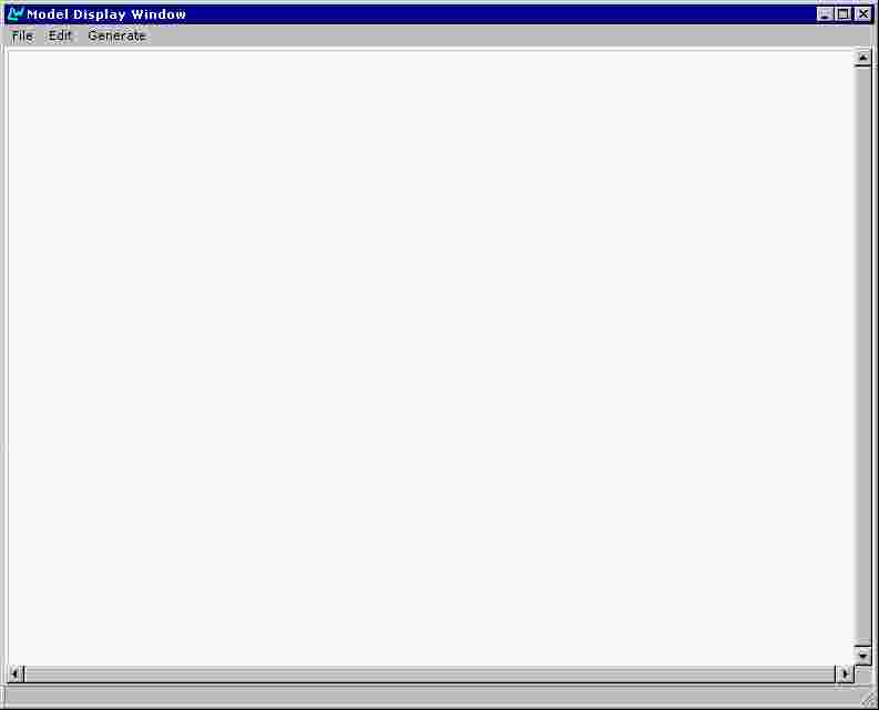
On starting up the AGILE system, the user is presented with an empty
Model Display Window. (Figure 3) which allows them to create, edit and
save the content specification of the desired text, and to launch the text
generation process. Title bars, menus and dialogue boxes are localised
to the user's preferred language, which defaults to the language setting
of the machine.
The Final Prototype retains the style of interaction implemented in the Intermediate Prototype. The user determines the desired content of the text through symbolic authoring. He or she progressively builds up the assertional content of the domain model via operations on a graphical interface.
The task of knowledge editing depends in an obvious way on the nature of the underlying knowledge representation. As explained in the AGILE deliverable MODL1 (Power, 1998), we follow LOOM and other languages of the KL-ONE family by making a basic distinction between terminological and assertional knowledge. The terminology, or T-box, defines the concepts from which a set of specific assertions (the A-box) can be configured. The task of defining the T-box is the responsibility of the developers of AGILE, not the users. It is the developers who specify that a procedure comprises a goal and a method, or that a button is a type of interface object and a possible candidate for a clicking operation. From the user's point of view, the T-box is fixed; the purpose of the knowledge editing tool is to exploit the conceptual resources of the T-box in order to build an A-box. In AGILE, an A-box is a set of assertions modelling a procedure for performing some task in a CAD/CAM application.
Knowledge editing in AGILE is a process of progressively extending a model until it is potentially complete. The knowledge editing tool must ensure that the model built by the user conforms to the conceptual definitions in the T-box, and hence that it lies within the scope of the language generators. In order to enforce this compliance, the user is required to begin from a procedure entity for which the goal and method properties are undefined. By clicking on labels signalling these undefined properties, the user obtains a list of suitable values: for instance, a goal can be an action of type create, draw, open, etc. Making a choice from this list introduces a new entity of the specified type. Through the concept definitions in the T-box, further properties will be associated with the new entity - for instance, a draw action will have an actee (the entity that is drawn) which must be some kind of line.
Since it is intended to support the production of instructional texts, the underlying domain model is essentially procedural. As described in deliverable MODL1, the main structure of the model is a set of procedures, each consisting of a goal and a method for achieving it. Methods are decomposed into one or more substeps (obligatory), a precondition (optional) and side-effects (optional). These can be specified in any order, but generation cannot occur if any obligatory elements have been left unspecified.
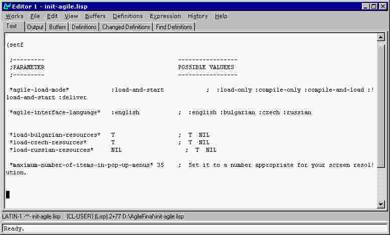
Changing the working languageSome of the parameters influencing the mode of the work of the AGILE system remain unchanged during a work session with the system. They are specified in a file init-agile.lisp located in the root directory of the AGILE system. The user may change their values before every work session. Among these parameters is *agile-interface-language* which specifies the working language during a session. Its possible values are :english, :bulgarian, :czech or :russian (Figure 4).
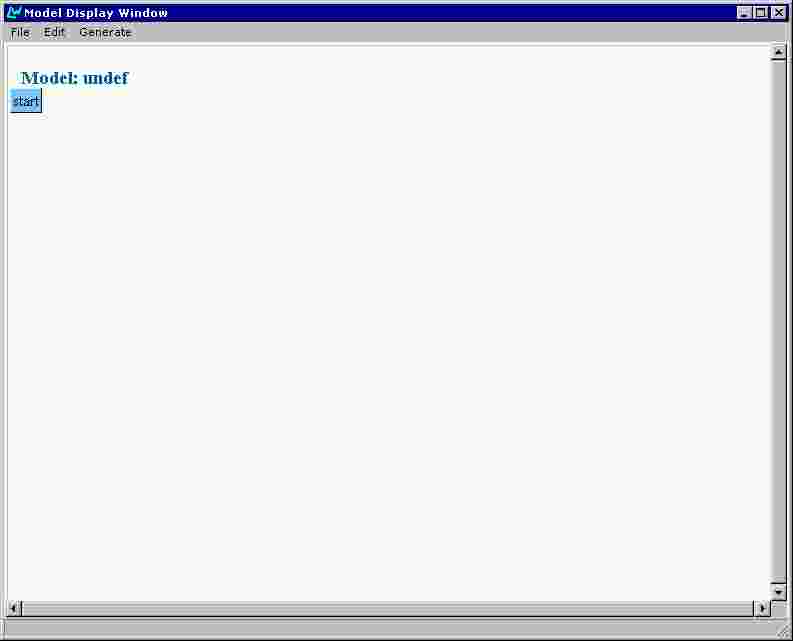
To open a new model, the user selects "New" from the File Menu (Figure 5). This produces a box labelled "Start" (Figure 6):
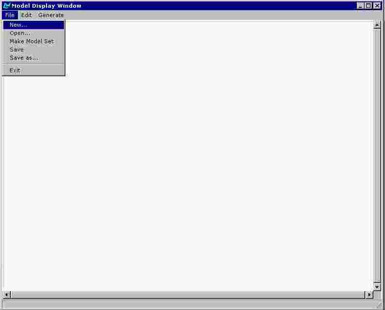
Figure 5. Opening a new model.
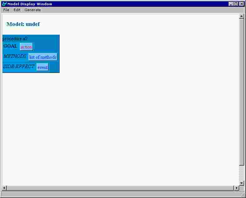
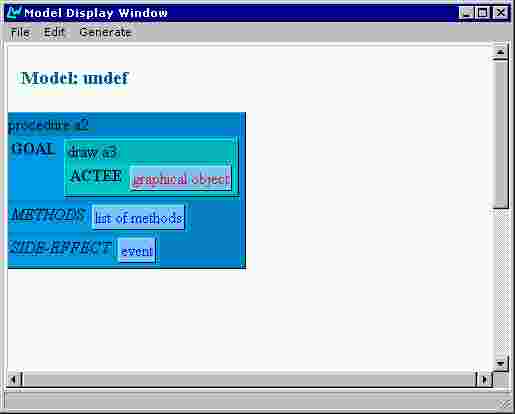
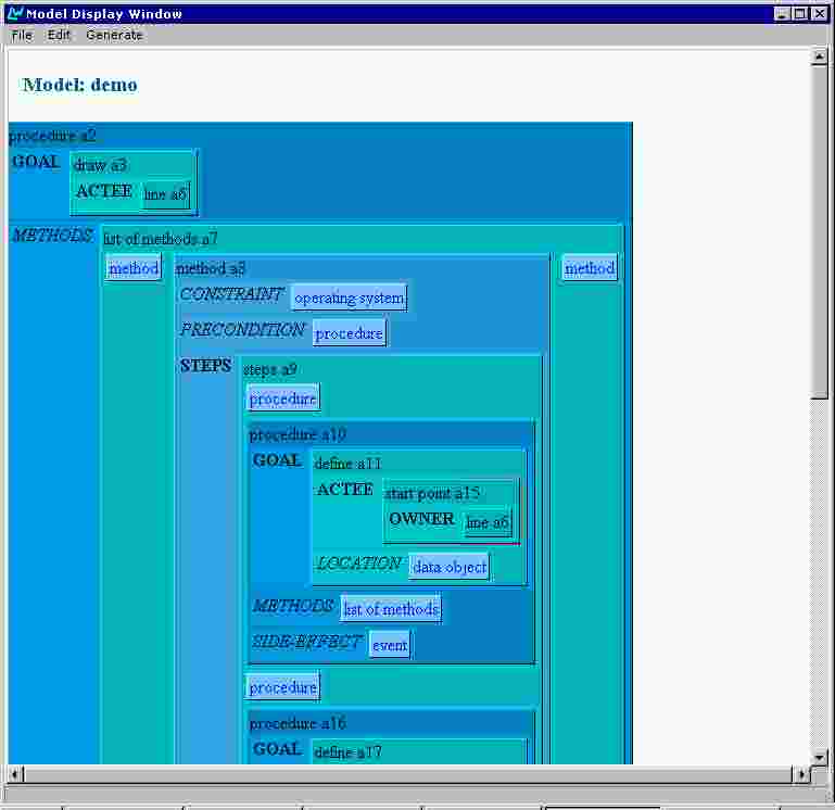
Clicking on this produces a graphical model of an empty procedure, with fields for its 3 components: goal, methods and side-effects (Figure 7). The user can then proceed to construct a model by editing this empty procedure.
The name of the model appears above the graphical representation of the model. The default name is 'undef'.
Every component of a model is represented as a pair of name and value (slot). The name is displayed as a label and the value is displayed as a differently coloured box.
AGILE supports users in editing models that have been previously constructed. To open an existing model, the user selects "Open" from the File Menu (Figure 8).
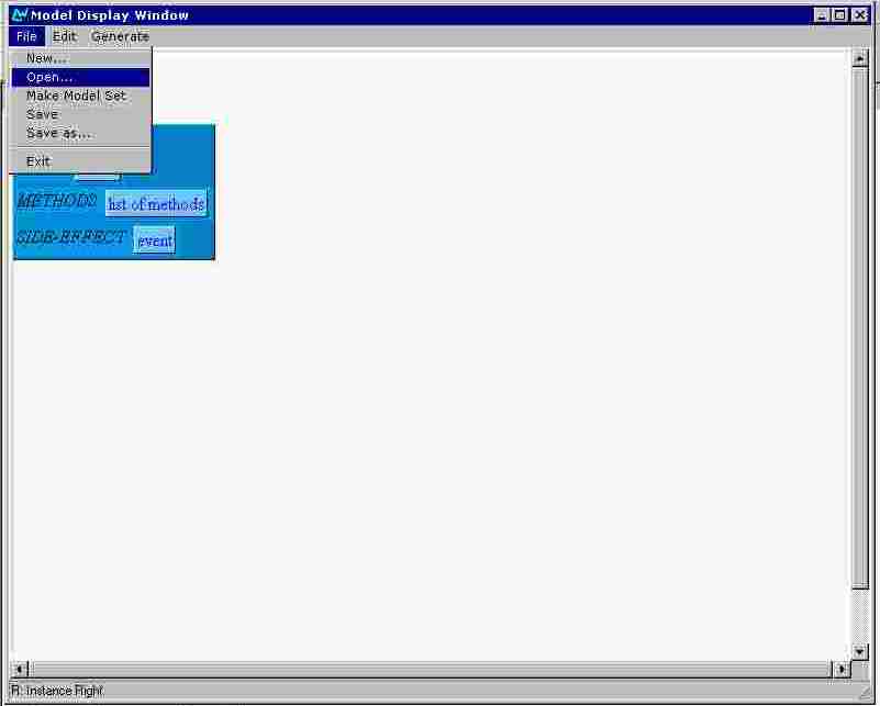
A standard dialogue-box (since it is a dialogue box of MS WindowsNT, it is not localised) for browsing the directory structure of the machine is then presented (Figure 9). Using this, the user selects the desired file; the model contained in this file is then presented on the screen (Figure 10).
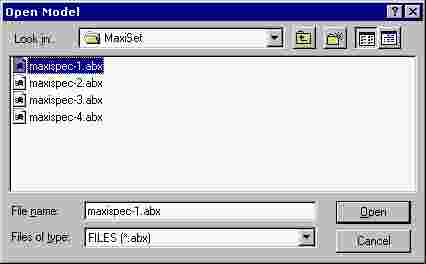
Figure 9. A model selection dialogue box.
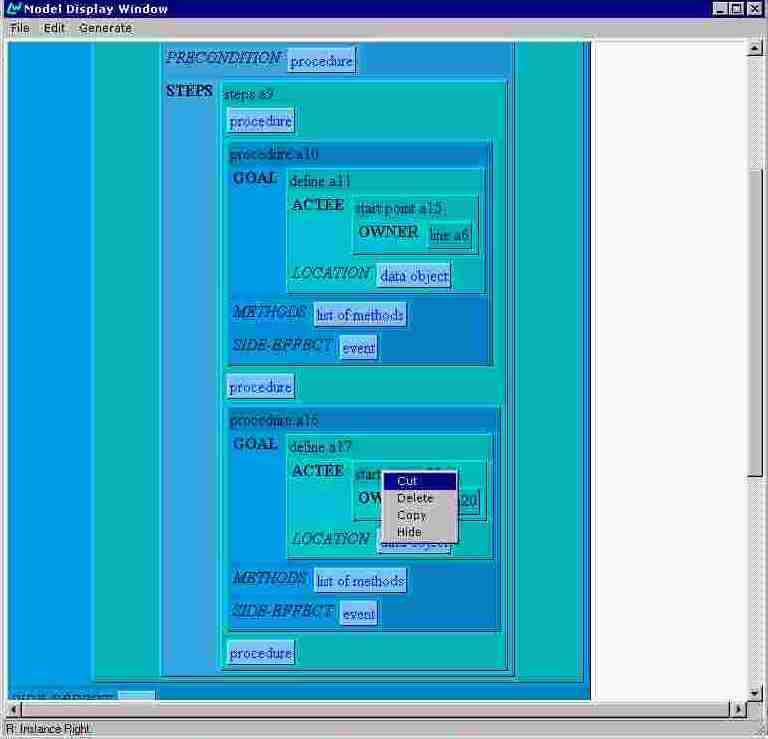
Editing operationsThe editing of a model is achieved mostly by opening drop-down menus via left or right mouse clicking on the model components. Left click on an unfilled attribute value opens menu with all appropriate values listed as options. Right click on a component opens menu providing some typical editing operations:
An example of task model editing
- Cut - removes the component from the model, but puts it in the editor's buffer
- Delete - removes the component from the model
- Copy - puts a reference to the component in the editor's buffer
- Paste As Copy (appears if the place clicked is appropriate for insertion) - creates a copy of the referenced in the buffer object and inserts it in the model at the position clicked
- Paste As Reference (appears if the place clicked is appropriate for insertion) - insert the reference from the editor's buffer at the position clicked
- Mark - marks the component for generation; this operation works on procedures.
- Unmark - unmarks the component if previously marked.
The basic editing techniques are presented and commented in the following example:
Let us assume that the user's goal is to build a model describing the procedure of drawing a line by specifying it's end points. The user starts a new model from the File menu as described above and clicks on the Start box. (see Figure 5, Figure 6 and Figure 7)
Note that the label Goal is displayed in bold, because it's slot filling is obligatory. Additional visual hint is the red color used for the value of the slot.
The slot Goal is not yet filled and action appearing as it's value is only the general concept, indicating the class of concepts which are appropriate.
The user clicks on action. A pull-down menu listing all appropriate domain concepts appears (Figure 11). The user chooses draw and the goal value changes to a box representing an instance of the concept draw (Figure 12). Note the a3 identifier. Every new instance is identified by an unique identifier (a3 in our example). This provides for distinction between different instances of a concept.
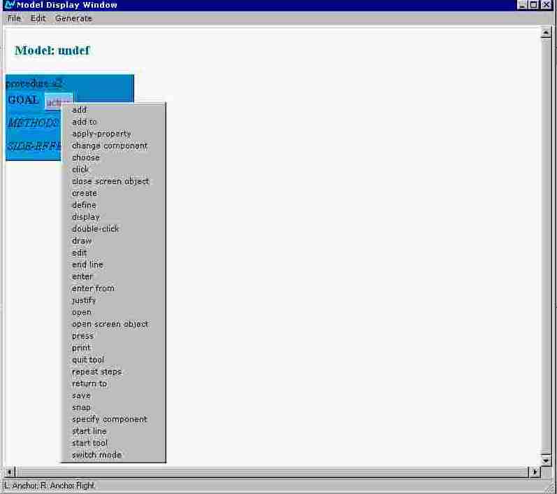
Figure 11. Context menu of all appropriate values.
The slot Actee is obligatory and the user clicks on its value box. A pull-down menu appears again (Figure 13). The user chooses line.
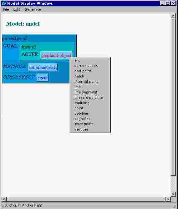
Figure 13. Context menu listing appropriate graphical objects.
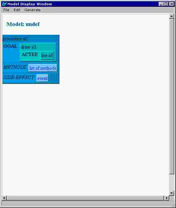
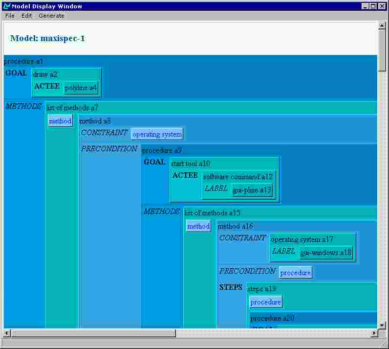
Then the user starts to specify the methods of drawing a line by clicking on list of methods. Thus a particular list of methods named a7 is created and it contains one empty method in the beginning (Figure 15). Clicking on method instantiates the concept and the method structure is unfolded (Figure 16).
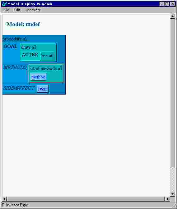
Figure 15. List of methods created.
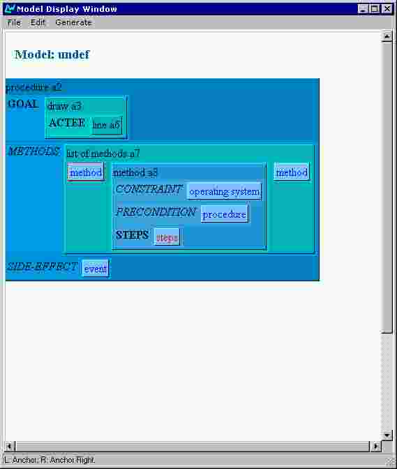
Note that two method boxes appeared left and right to the instantiated method. These allow the user to insert methods at any position in an existing list of methods.
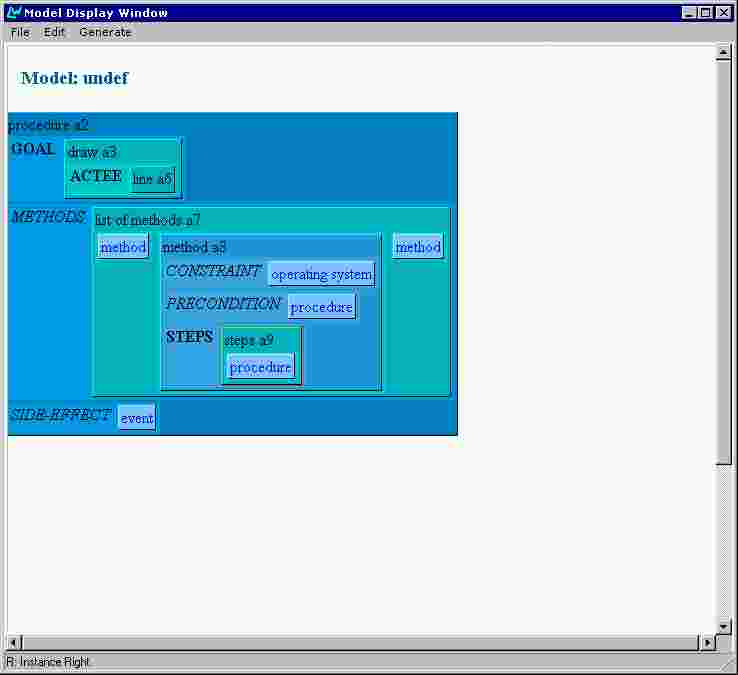
Figure 17. Steps concept instantiated.
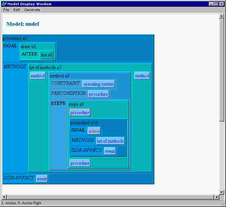
To proceed with specifying the steps of the method the user clicks on steps. The concept steps is instantiated as object a9 and an empty procedure appears as it component (Figure 17). Similarly to the situation with methods, when the empty procedure is instantiated (Figure 18) two new empty procedures appear above and below it. Note the vertical layout of the list of procedures providing for easier visual distinction as different from the horizontal layout of methods.
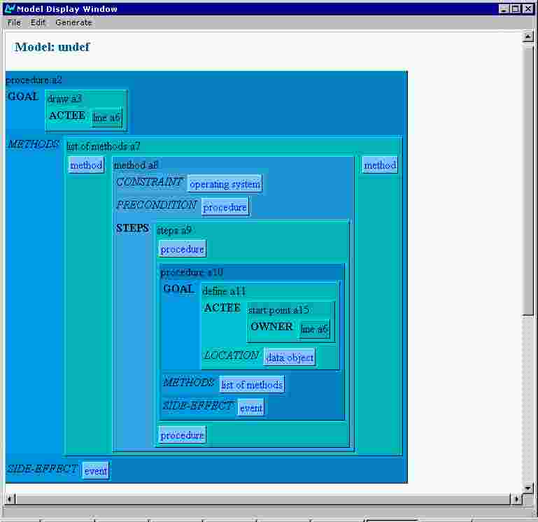
Then the user continues by specifying the goal of the new procedure as define and its actee as start point (Figure 19).
Since the start point, just specified, is a point of the line already instantiated as a6, the user have to put a reference to a6 as a value of the owner attribute. This is achieved by the following actions:
- right-clicking the line a6 box (Figure 20) and choosing copy puts a reference to the object in the editors copy buffer;
- right-clicking the graphical object box (Figure 21) and choosing Paste As Reference pastes the same reference as a value of owner (Figure 22).
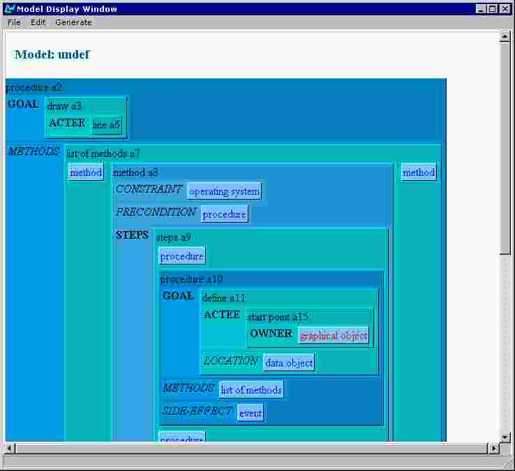
Figure 19. Specifying the actee of the concept 'define'.
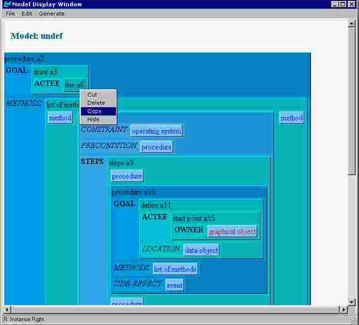
Figure 20. Copying an existing component.
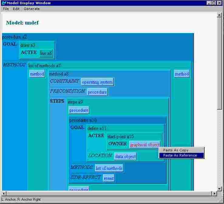
Figure 21. Pasting as reference.
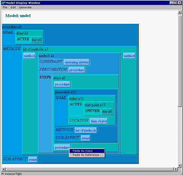
The next step in the list of steps has to be defining of the line end-point. The corresponding procedure component could be built from scratch as the previous one, but let us consider an alternative technique in order to demonstrate pasting of copy.
So, the user copies the whole procedure a10 structure (Figure 23) and pastes a copy of it as next step (Figure 24). Note that every instance in the resulting procedure a16 has new identifier (Figure 25).

Figure 23. Copying a structure.
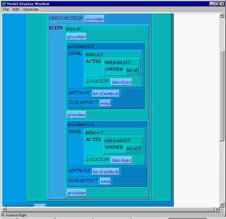
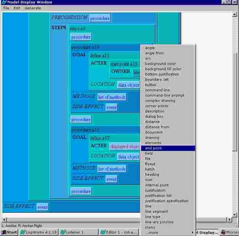
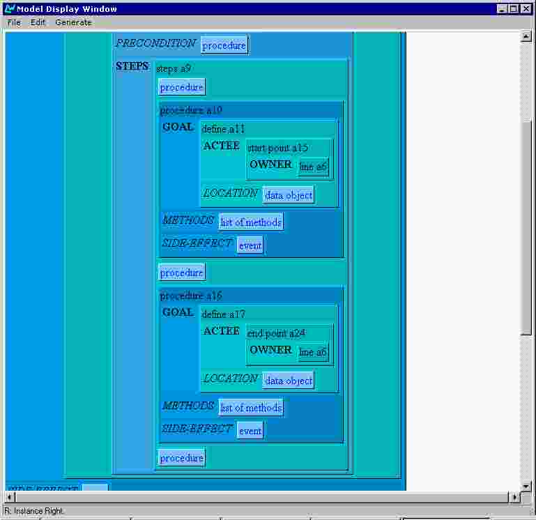
Now the user deletes the start point a19 component (Figure 26) and creates an end-point instance in its place (Figure 27 and Figure 28). Note that copying the reference to line a6 as owner of the end-point have to be done again.
Deleting components can be achieved by choosing either Delete or Cut from the context menu. The difference (as Windows tradition) is that Cut puts the object into the editors buffer, thus making its pasting possible.
The user saves the model by choosing Save or Save As from the File menu (Figure 29). A standard WindowsNT dialogue box appears (Figure 30) where the user specifies the directory and the file name. The system maintains consistency between the model name and the saved file name. When a model is saved under new file name, the model name is automatically set to the same name (without the file name extension) (see Figure 31).
Figure 30. The Save Model dialogue box.
A model in the AGILE system represents a procedure with its goal and method(s), but certain text types, namely overviews and functional descriptions, are generated over lists of procedures. The AGILE system interface provides for model sets composing and editing.
The user composes a set of already created and saved models by choosing 'Make a Model Set' from the File menu. The standard dialogue box for specifying a model to be opened appears. The user selects a model and clicks 'OK'. The dialogue box appears again, giving the user chance to select the second model, etc. This process continues until the user clicks on 'Cancel'. Then all selected models are composed and displayed in the Model Editor window as a sequence of procedures. The user may then edit the composed model set as 'normal' model and to initiate text generation.
Setting the parameters of the output text(s)The user selects "Preferences" from the Generate Menu. A dialogue box presenting all the following options is then presented (Figure 32).
 Generating and viewing text
Selecting the text type(s)The user can select any or all of the five text types (Overview, Long Instructions, Short Instructions, Function oriented Functional Description, Object oriented Functional Description) via check boxes.
Selecting the text style(s)The user can select, via radio buttons, one of the three styles for the text types Long Instructions, Short Instructions, Function oriented Functional Description, Object oriented Functional Description. Additionally, the user can select one of the two styles of side-effects for Long Instructions text type. Detailed descriptions of the various style parameters are provided in deliverable SPEC2.
Selecting the output language(s)The user selects via tick boxes, any or all of the four output languages
Generating text(s)Notes on the implementation of the knowledge editor
- partial generation (using MARK). While editing a model or a model set the user can mark one or several procedures. The 'Mark' operation appears as option in the right click context menu, when the clicked object is a procedure (see Figure 23). If there are any marked procedures and the user selects "Marked" from the Generate menu, a new temporary list of all marked procedures is composed and passed to the generation module.
- full generation. The user initiates the text generation over the whole model (or model set) by selecting "All" from the Generate menu (Figure 33).
Viewing the generated text(s) 
The generation results are visualized in a separate Internet Explorer's window for every generation language. Figure 34 shows the result of a generation in Bulgarian language, while the working language was English. The window is split in three frames. The top frame presents information about the generation options and a time stamp. It's localized in the working language, while the left and the right frames are localized in the particular generation language. The right frame document presents the generated text. The left frame displays a table of contents, where every item is clickable and is a hyperreference to the relevant place in the right frame.
A separate IExplorer window is opened automatically for every generation language and for every new model.
Consider the following example. The user edits a model named "demo" and starts generation in Czech and Russian languages. The results will be displayed in two windows. Then the user edits further the model and starts generation for Russian and Bulgarian languages. The result for Russian replaces the previous result in the Russian window and a new window is opened for the Bulgarian. The Czech window remains unchanged. Then the user makes some more changes of the model, saves it under new name, and starts generation for Czech and Bulgarian. Two new windows open for the new Czech and Bulgarian results because of the changed model name.
The opened IExplorer windows are never closed automatically. The user have to close them manually if and when he/she wants. The reason behind this behaviour is that the user might want to inspect the generated texts for longer time and to compare the results obtained from different versions of the model.
Saving the generated textsIn the process of generation the text generation module produces texts formatted with HTML tags. The interface module composes these texts and wraps them in the appropriate HTML tags to obtain complete HTML documents for every generation language. The interface module then generates the table of contents HTML document (displayed in the left frame), the information HTML document (top frame) and the HTML document defining the frame set layout.
All these documents are automatically saved as HTML files in the directory where the model is saved. The file names are composed from the model name, generation language and the text style option used.
For instance, the generated text document (right frame) in the previous example (Figure 34) is saved as demo-BULGARIAN-PERSONAL-text.html. Such organization makes convenient further editing and composing in larger HTML documents using an HTML authoring tool.
The knowledge editor is programmed in Harlequin LispWorks 4.1 with the extensive use of CLIM (Common Lisp Interface Manager). Runs on Windows NT.
We used the DDE protocol to communicate the Microsoft Internet Explorer from within lisp, but the DDE documentation (we found on the Internet) is not very detailed. For example, a problem we encoutered was that when a HTML file is displayed, then updated and a DDE request for displaying again the file is sent to the Internet Explorer, the window's content doesn't refresh, despite including HTML tags prohibiting the use of a cached copy. Since we couldn't find information for such a problem in the Internet Explorer's DDE documentation, currently the interface module of the AGILE system generates and includes in the generated HTML files relatively complex JavaScript code, which recognizes this situation and forces window refreshment.
The inner details of supporting non-English alphabets differ (and are poorly documented) through the versions of Microsoft Windows operation system. This is the only reason to restrict the using of the AGILE system on WindowsNT only.